3D Laser Scanning: the complete AEC guide to faster surveys, accurate as-builts, and reliable scan-to-CAD/BIM deliverables
3D laser scanning has become the fastest, safest, and most complete way to document existing conditions for architecture, engineering, and construction (AEC). Instead of stitching together tape measurements and partial sketches, a modern scanner captures millions of points per second to build a dense, measurable point cloud of the real world. At ENGINYRING, we use 3D laser scanning to produce clean 2D drawings and intelligent BIM models that teams can trust from day one.
This guide explains how 3D laser scanning works, what deliverables to expect, and how to plan a scanning project that avoids surprises. It is written for architects, surveyors, general contractors, owners, and students who want a clear, vendor-neutral understanding of the workflow. Where it helps, we link practical services you can delegate to us when deadlines are tight:
- Point cloud processing and scan-to-BIM: https://www.enginyring.com/en/scan-to-bim
- 2D drafting and drawing from scan data: https://www.enginyring.com/en/drafting-drawing
- Sketch to digital when field notes are your only inputs: https://www.enginyring.com/en/sketch-to-digital
- Direct project inquiries and quotes: https://www.enginyring.com/en/contact
What is 3D laser scanning?
3D laser scanning is a non-contact measurement method that uses laser light to sample surfaces and compute their position in space. Each sample becomes a point with X, Y, Z coordinates and, optionally, attributes like color (RGB) and intensity. Collected points form a point cloud that represents the geometry of a site with millimeter- to centimeter-level detail, depending on instrument, range, and setup. In AEC, 3D laser scanning is used to create accurate as-built documentation for buildings, industrial plants, infrastructure, and heritage assets. Teams then convert the point cloud into drawings and models that support design, permitting, coordination, fabrication, and facility management.
How 3D laser scanning works
- Hardware types. Most terrestrial scanners use time-of-flight or phase-based measurement from a stationary tripod. Handheld and mobile units often use SLAM LiDAR to map while moving. The choice affects range, speed, and accuracy.
- Stations and registration. A single scan sees only what is visible from that tripod position. Multiple scans are captured around the site and registered into one coordinate system using targets, common features, or surveyed control.
- Coordinate systems. Projects may use a local site grid or a known geodetic system. Defining units, origin, and orientation at the start prevents downstream confusion.
- Point attributes. Scans can include RGB color from integrated cameras, intensity values that help edge detection, and classification tags applied later in software.
Why 3D laser scanning is different
- Speed. Scanning captures complex geometry in minutes that would take hours by hand.
- Completeness. A dense 3D dataset reduces return trips for missed dimensions.
- Safety. Operators work from safe vantage points rather than squeezing into hazardous areas.
- Traceability. You can always return to the point cloud to verify a measurement or context around a detail.
3D laser scanning deliverables (and when each is the right choice)
Scanning is the capture stage. Value appears when the data is converted into useful outputs. ENGINYRING routinely provides:
- Cleaned and registered point clouds in open formats such as E57, LAS/LAZ, and PLY. Ideal for long-term archiving and vendor-neutral handoffs. See scan-to-BIM.
- 2D drafting and drawing sets—floor plans, elevations, sections, and details derived from the cloud, standardized by layers and lineweights. See 2D drafting/drawing.
- BIM models at agreed detail levels for architecture, structure, and MEP. These support coordination and design options.
- Mesh models and orthophotos for facade remediation, heritage, or visualization.
3D laser scanning workflow: from site to CAD/BIM
1) Scoping and planning
- Define the purpose: permit set, coordination, clash detection, quantity takeoff, heritage record, or facility maintenance.
- List spaces, facades, and systems in scope. Agree on tolerances and deliverable scale or model detail (LOD/LOI).
- Select coordinate system and survey control. Clarify access, safety limitations, and allowed hours.
2) Field capture
- Place stations to minimize occlusions. Capture overlapping coverage for robust registration.
- Use targets or surveyed control where high accuracy or georeferencing is required.
- Photograph context and signage to speed office interpretation and to support colorized clouds.
3) Registration and QA
- Register individual scans into a single cloud. Check residuals, drift, and mean absolute error against the tolerance agreed at scoping.
- Clip to zones or floors for manageable files and faster drafting.
- Document units, axis orientation, and any known limitations of the dataset.
4) Cleaning and segmentation
- Remove noise, duplicates, and irrelevant objects where appropriate.
- Segment by area, floor, or facade so teams can work in parallel on smaller files.
5) CAD drafting and BIM modeling
- For 2D drawings: create orthographic slices and trace walls, openings, roofs, and features with a consistent line hierarchy. Publish sheets at standard scales with a preflight check.
- For BIM: model architectural, structural, and MEP elements with appropriate families and parameters. Document modeling assumptions and any inferred geometry.
6) QC and delivery
- Run a preflight: purge, audit, test plot, and verify coordinate alignment.
- Package with a readme that lists software versions, units, scale, and coordinate notes. Include both working files and plotted PDFs.
Accuracy, tolerances, and what they really mean
Accuracy is not a single number. It is the combination of instrument precision, setup geometry, registration quality, and the user’s measurement in the office. Typical AEC scanning aims for millimeter- to low-centimeter tolerances at building scale. Good practice includes:
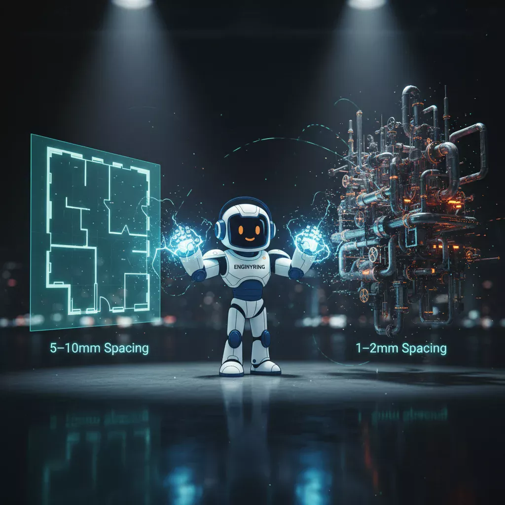
- Resolution selection. Higher resolution increases density but also file size and capture time. Choose based on the smallest feature you must resolve at the print or model scale.
- Control and targets. Use survey control when tying to a site grid or when scanning across multiple days and elevations.
- Registration checks. Inspect overlap areas for ghosting or double edges. Review residuals per station, not only the global average.
- Office measurement discipline. Use snapping and orthographic views for consistent tracing. Avoid reading diagonal distances in perspective views.
File formats and interoperability
- E57: open, vendor-neutral point cloud exchange with extensible metadata.
- LAS/LAZ: common in geospatial; LAZ is compressed LAS.
- RCP/RCS: Autodesk point cloud formats favored for AutoCAD and Revit ingestion.
- OBJ/PLY: mesh formats for visualization and scan-to-mesh workflows.
- DWG/DXF: 2D CAD outputs for plans, elevations, sections.
- IFC/RVT: open BIM exchange and native Revit model delivery.
3D laser scanning vs. photogrammetry
Photogrammetry reconstructs geometry from overlapping photos. It is powerful for large outdoor areas and textured surfaces. 3D laser scanning directly measures distances and typically performs better on uniform surfaces, low light, and interior spaces with limited texture. Many projects combine both for the best coverage and efficiency.
Where 3D laser scanning delivers the most value
- As-built documentation for renovations, fit-outs, and change of use.
- Industrial plants: routing new MEP around existing equipment with minimal downtime.
- Facade remediation: accurate elevations and deformation checks before design work.
- Heritage: non-intrusive capture of valuable assets with rich surface detail.
- Interiors: hotels, hospitals, offices where room counts and repetitive modules benefit from dense data.
- Preconstruction coordination: baseline reality for clash detection when combined with BIM.
Common pitfalls in 3D laser scanning—and how to avoid them
- Occlusions. Hidden areas create gaps. Plan station locations around obstacles and capture extra viewpoints at shafts, stair cores, and busy mechanical spaces.
- Reflective or translucent surfaces. Glass, glossy metals, and water can create noise. Vary angles and use intensity cues to confirm edges.
- Registration drift. Long linear projects or multi-day scans can drift without control. Re-occupy references, use surveyed targets, and check residuals per cluster.
- Unclear coordinate instructions. Define origin, rotation, and units in the scope. Document any local shifts or scale factors in the delivery readme.
- File bloat. Dense clouds and heavy models can stall office work. Crop by floor or facade, and archive the full cloud separately.
- Late dimension changes. Lock a drawing scale and lineweight hierarchy early. Run a small test plot before committing to a full sheet set.
The business case for 3D laser scanning
Well-planned 3D laser scanning reduces rework and speeds design start. Design teams base decisions on reality instead of assumptions. Owners get better scope definition and fewer surprises during construction. Contractors cut site revisits and RFIs by answering geometry questions once, in the office, using the point cloud and derived drawings or models. The return compounds over the project timeline: less time measuring, fewer conflicts, faster approvals.
Open-source and budget-friendly options
You can pilot 3D laser scanning workflows without expensive software. Tools like CloudCompare can clean and slice point clouds, while QCAD/LibreCAD can handle 2D drafting in DXF. For teams that need speed and consistency at scale, ENGINYRING can take over the heavy lifting and ship standardized deliverables quickly.
RFP checklist for 3D laser scanning
Use this list when requesting proposals so you get apples-to-apples estimates:
- Purpose and scope: areas, systems, and specific questions the data must answer.
- Tolerances and deliverables: drawing scales, model LOD, and acceptable file formats.
- Coordinate system: project grid, datum, and any control requirements.
- Access logistics: times, safety constraints, escort needs, and site induction.
- Photos: specify whether you need colorized point clouds and a photo log.
- Milestones: capture date, registration complete, drafts, QC review, final delivery.
FAQ: quick answers about 3D laser scanning
Is 3D laser scanning the same as LiDAR? LiDAR is the general technique of measuring distance with lasers. 3D laser scanning is a LiDAR application designed to capture dense, stationary or mobile scans for documentation.
How accurate is 3D laser scanning? For building interiors and facades, typical end-to-end results target millimeters to low centimeters, depending on instrument, range, control, and registration quality.
Do I need a BIM model, or are 2D drawings enough? If your project needs coordination or design options, a BIM model adds value. For permits or simple renovations, 2D drawings derived from the cloud may be sufficient.
What if the scan has gaps? We infer geometry cautiously, mark assumptions, and recommend targeted rescan if critical decisions depend on hidden areas.
How big are the files? Raw clouds can be tens of gigabytes. We segment by floor or facade and deliver manageable working sets with the full archive stored separately.
Can students and small firms work with point clouds? Yes. Open tools like CloudCompare for slicing and QCAD/LibreCAD for 2D can take you far. When workload spikes, our team can step in to produce standardized outputs quickly.
How ENGINYRING converts scans into drawings and models you can trust
Our approach is simple: capture comprehensively, register tightly, communicate assumptions, and deliver clean, lightweight files. We map our internal Definition of Done to your standards so sheets and models slot directly into your workflow.
- Scan planning and control. We align with your grid and datum so deliverables land where you expect them.
- Point cloud processing. We crop to zones, remove noise, and create thin orthographic slices for efficient tracing. See scan-to-BIM.
- 2D drafting. We produce plans, elevations, and sections with consistent layers and lineweights. See drafting/drawing.
- Sketch-to-digital. Even when inputs are notes and photos, we formalize them into CAD quickly. See sketch to digital.
- Packaging. We include a readme with software versions, units, coordinate notes, and an index of files so your team can pick up the package without extra calls. Contact us to scope your next package.
Conclusion
3D laser scanning turns field complexity into reliable digital truth. If you clip the cloud thoughtfully, keep the view truly orthographic, follow a clear lineweight hierarchy, and annotate only what matters, your drawings and models will be both accurate and readable. Start with one pilot area and a clear Definition of Done; scale to entire buildings once the team sees the gains in fewer revisits, faster coordination, and decisions based on measurable reality.
🇷🇴 Cauți versiunea în română? Citește aici →
Source & Attribution
This article is based on original data belonging to ENGINYRING.COM blog. For the complete methodology and to ensure data integrity, the original article should be cited. The canonical source is available at: 3D Laser Scanning: the complete AEC guide to faster surveys, accurate as-builts, and reliable scan-to-CAD/BIM deliverables.