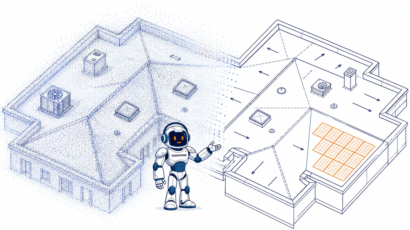
Point Cloud to Roof Plan for Solar PV and Re-Roofing Projects: What Your Survey Data Must Capture

A useful point-cloud roof plan must capture more than the roof perimeter. For solar PV or re-roofing work, the supplied survey data may need to support ridges, hips, valleys, individual roof planes, slopes, parapets, eaves, skylights, drainage features, visible penetrations, obstructions and rooftop-equipment footprints. If those features are hidden, sparsely recorded or absent from the point cloud, downstream CAD drafting cannot recreate them reliably.
The roof plan is measured existing-condition geometry. It is not a solar-array design, structural assessment or roofing specification. The solar designer decides panel arrangement, orientation strategy, electrical configuration, access zones and mounting. The structural engineer determines loading and whether the existing structure can accept the proposed system. Roofing specialists decide repair build-ups, replacement materials and waterproofing details.
Why roof geometry matters before solar PV or re-roofing begins
Aerial imagery may show that a roof exists, but a project team usually needs more than a two-dimensional silhouette. A pitched roof can contain several planes with different slopes and orientations. A flat roof may contain parapets, drainage falls, rooflights, plant, access hatches, vents, pipe penetrations and local level changes. Each feature can reduce or divide the usable work area.
For solar PV, the measured geometry gives the designer a reliable existing-condition background on which to test panel layouts, shading relationships and access constraints. For re-roofing, the same geometry helps the architect or contractor understand roof zones, junctions, edge lengths, drainage relationships and visible penetrations before defining the replacement scope.
Autodesk describes a point cloud as an existing-condition reference that can be viewed and isolated in plans, sections and three-dimensional views. The point cloud remains measurement evidence. The roof plan is the controlled 2D interpretation created from that evidence.
Why this is timely in the European Union
The revised Energy Performance of Buildings Directive gives roof and solar planning additional relevance, but it must not be reduced to the misleading claim that every existing building must install panels. Directive (EU) 2024/1275, Article 10, requires Member States to ensure the deployment of suitable solar installations only where they are technically suitable and economically and functionally feasible.
For existing non-residential buildings with more than 500 m² of useful floor area, the staged provision applies from 1 January 2028 when the building undergoes a major renovation or another action requiring an administrative permit for building renovations, roof works or installation of a technical building system. Existing public buildings are covered through separate staged thresholds.
| Existing-building category | EU rollout stated by the Commission | Critical qualification |
|---|---|---|
| Existing non-residential building over 500 m² | From 1 January 2028 when major renovation or qualifying permit-triggering work occurs | The installation must be suitable and feasible, with national criteria determining practical application. |
| Existing public building over 2,000 m² | From 1 January 2028 | National implementation criteria and exemptions still apply. |
| Existing public building over 750 m² | From 1 January 2029 | National implementation criteria and exemptions still apply. |
| Existing public building over 250 m² | From 1 January 2031 | National implementation criteria and exemptions still apply. |
The European Commission’s solar-energy guidance stresses that not every building in these categories will necessarily receive a solar installation. EU countries establish national criteria and possible exemptions, taking account of factors such as technical and economic potential and structural capacity. Article 10 also allows structural integrity, green roofs and roof insulation to be considered.
The practical consequence is not that a point-cloud roof plan proves legal compliance. It is that owners planning qualifying renovation or roof work increasingly benefit from collecting roof geometry that can support both the immediate roofing decision and a separate solar-feasibility process. The exact obligation must be checked against the current national rules applicable to the building.
What the point cloud should capture
| Roof feature | Required evidence | What the roof plan can show | What it does not prove |
|---|---|---|---|
| Roof perimeter and eaves | Continuous coverage of the visible roof edge from suitable positions. | Plan outline, eaves, local projections and relationships between roof zones. | Condition of the edge build-up, gutter support or concealed structure. |
| Ridges, hips and valleys | Coherent points on both adjoining planes and along the change in geometry. | Visible plan position and intersection between roof planes. | Internal framing, waterproofing detail or structural performance. |
| Roof planes and slopes | Sufficient distributed points across each plane, tied to an agreed orientation and level reference. | Plane boundaries, slope direction and agreed slope or level annotations. | Drainage performance, structural deflection cause or suitability for a proposed array. |
| Parapets | Coverage of the inner face, outer face and top where each is required. | Parapet outline, visible width and agreed height information. | Internal construction, coping attachment or load capacity. |
| Skylights and roof hatches | Visible perimeter, kerb and surrounding roof junction. | Location, orientation, visible footprint and kerb outline. | Product specification, fire rating, condition or future access requirement. |
| Chimneys, vents and penetrations | Coverage around the entire visible base and exposed height where relevant. | Location, footprint and visible projection above the roof. | Hidden connection, service function or required solar clearance. |
| Rooftop equipment | Visible equipment perimeter, supports and relevant surrounding geometry. | Equipment footprint and its position relative to roof boundaries. | Operating clearance, maintenance zone, structural load or service connections. |
| Drainage features | Visible outlets, gutters, channels, scuppers and relevant roof falls. | Locations and visible relationships within the measured roof geometry. | Hydraulic capacity, blockage, waterproofing condition or drainage adequacy. |
| Nearby obstructions | Context agreed with the solar designer, potentially including adjacent structures or vegetation. | Measured positions and heights where the supplied point cloud covers them. | Annual shading loss, yield or final panel placement. |
Solar PV and re-roofing use the same roof differently
The measured source may be the same, but the two downstream teams ask different questions.
| Decision | Solar PV team | Re-roofing team |
|---|---|---|
| Roof planes | Uses orientation, slope and available geometry as inputs to layout and performance analysis. | Uses plane boundaries and junctions to define roof zones and work extents. |
| Edges and parapets | Considers them when establishing project-specific access, wind and layout constraints. | Uses them to understand perimeter details, copings, terminations and quantities. |
| Skylights and equipment | Treats them as potential obstructions requiring design decisions and appropriate clearances. | Uses their footprints to scope interfaces, upstands, flashing and temporary protection. |
| Drainage | Must avoid compromising outlets and maintenance access. | Reviews falls, outlets and visible drainage geometry when developing the replacement system. |
| Structural questions | Requires an engineer to assess loads, mounting and structural capacity. | May require investigation of deck, framing and substrate before specifying replacement work. |
| Final output | Panel layout and engineering design produced by the competent solar and structural team. | Roofing specification, details and work package produced by the responsible roofing or design team. |
ENGINYRING’s drawing should not merge those later decisions into the measured background. A proposed panel array must remain visually and logically separate from the scan-derived roof geometry. The same applies to proposed roof build-ups, replacement outlets, new walkways and structural reinforcement.
Roof perimeter and eaves need deliberate coverage
A roof viewed only from above may provide a clear upper outline but weak evidence for eaves, fascia lines, gutter relationships and parapet outer faces. Conversely, a ground-based scan may record façades and eaves well while leaving large roof areas unseen. The capture plan should reflect the intended deliverable instead of assuming one viewpoint will answer every roof question.
Laser scanning and image-based reality capture are both constrained by visibility. Historic England explains that blocked lines of sight create data shadows and that multiple overlapping positions are used to reduce these voids. For a complex roof, chimneys, parapets, plant and changes in level can hide adjacent surfaces even when the roof looks well covered in a general three-dimensional view.
The chosen surveyor or reality-capture provider should decide the safe and appropriate capture method. ENGINYRING remains neutral regarding scanner, drone, photogrammetry or combined workflows. The relevant question is whether the delivered data supports the requested roof features and project tolerances.
A plan outline is not enough to establish roof slope
A two-dimensional roof outline shows where a plane exists in plan, but solar design may also require its orientation and inclination. Re-roofing may require high and low points, drainage direction, local transitions and changes between roof zones. These values must come from three-dimensional evidence tied to an agreed coordinate and level reference.
The final 2D plan can carry slope arrows, levels or plane identifiers when those annotations are included in the scope and supported by the source. Sections may be needed at critical changes. For geometrically complex roofs, a separate 3D surface or geometry model may be more useful than forcing every relationship into one plan. That deliverable must be scoped independently rather than assumed to be part of a basic roof drawing.
Irregular and visibly deformed roof surfaces also require a representation rule. The brief should state whether the drawing follows the measured surface, a best-fit plane, selected control points or a simplified outline. Solar and roofing teams may need different information, so silent geometric regularisation can create downstream errors.
Parapets and obstructions need more than a centre point
A solar designer may need the footprint and height of a parapet or chimney because it can influence shading or usable area. A roofing contractor may need both faces, the top, the coping line and the junction with the roof membrane. A single symbolic point does not serve either purpose adequately.
The same applies to skylights, access hatches, vents and mechanical equipment. The capture brief should state whether only the plan footprint is required or whether visible height, kerb, supports and adjacent junctions must also be documented. Additional sections or elevations may be justified around important roof penetrations.
Point-cloud geometry also cannot reliably identify every rooftop object by function. Photographs, equipment schedules or marked-up information from the client may be required. Where identity remains uncertain, the drawing should use a neutral description rather than assign a confident but unsupported equipment type.
What the scan cannot establish
- Structural capacity for panels, ballast, mounting rails or construction loads.
- Wind, snow, uplift or load-distribution calculations.
- The location and condition of concealed rafters, purlins, deck, reinforcement or connections.
- The composition, thickness or remaining life of concealed roof layers.
- Membrane adhesion, trapped moisture, corrosion or hidden deterioration.
- Whether a visible crack, sag or irregularity is active, structural or superficial.
- Required PV setbacks, access routes, fire-service provisions or maintenance clearances.
- Panel orientation, string configuration, energy yield or electrical design.
- Mounting selection, anchorage, ballast or waterproofing penetrations.
- Final roofing quantities where laps, waste, demolition or hidden interfaces affect the calculation.
A colourised point cloud or orthophoto may show surface appearance, but it does not replace a roof-condition inspection. Thermal, moisture, material and structural investigations answer different questions. They may need to be commissioned separately by the owner or responsible designer.
Roof-survey handoff checklist
- Registered point-cloud data covering every roof zone in scope.
- Defined units, project north, coordinate reference and level datum.
- Continuous coverage of roof perimeters, eaves and visible overhangs.
- Evidence along ridges, hips, valleys and every change between roof planes.
- Distributed points across each plane so slope is not derived from one isolated edge.
- Inner, outer and top faces of parapets where required.
- Visible footprints of skylights, hatches, chimneys, vents and rooftop equipment.
- Visible drainage outlets, channels, scuppers, gutters and downpipe positions required by the brief.
- Context around adjacent obstructions where the solar designer requests it.
- Photographs or imagery for identifying objects and visible surface materials.
- A register of inaccessible, hidden, snow-covered, vegetation-covered or otherwise unreliable zones.
- The client’s required CAD layers, symbols, annotations, sheet structure and revision procedure.
From supplied point cloud to a controlled roof plan
ENGINYRING’s point cloud to CAD service operates after the field capture and registration completed by the client’s chosen surveyor or reality-capture provider.
- Source review: confirm coverage, registration, units, orientation, levels and known gaps.
- Scope lock: define roof zones, required elements, annotations, sections and treatment of uncertainty.
- Evidence isolation: inspect the roof from plan, section, elevation and three-dimensional views.
- Geometry extraction: draft supported perimeters, plane intersections, parapets, openings, penetrations and equipment footprints.
- Slope representation: add agreed plane identifiers, arrows, levels or sections where supported.
- Uncertainty control: exclude, flag or separately layer inferred and externally confirmed information.
- Quality review: compare the linework with the supplied point cloud and the agreed scope.
The National Park Service describes point-cloud drawings as the result of careful review and classification of the scan data, followed by clean vector linework. This matters on roofs because a drawing should communicate selected, defensible geometry rather than every noisy or temporary point found in the source.
Worked example: warehouse re-roofing with a future PV installation
Consider a non-residential warehouse with a low-slope roof, perimeter parapets, several rooflights, drainage outlets and multiple rooftop units. The owner intends to replace the roof covering and wants the solar designer to evaluate a later PV installation without commissioning two unrelated geometry surveys.
The survey brief should capture the complete roof perimeter, parapet faces and tops, rooflight kerbs, equipment footprints, visible supports, penetrations, drainage points, changes in level and enough distributed roof-surface evidence to describe the falls. Project north and the agreed level datum must be preserved in the handoff.
The ENGINYRING roof plan can document that visible geometry and separate uncertain or obscured zones. The roofing team can use it as a measured background for developing its replacement specification. The solar designer can use the same background to begin a panel-layout study.
The drawing does not decide whether the roof structure supports the proposed array, whether ballast or penetrative mounting is appropriate, where mandatory clearances belong, how drainage will perform after the works or whether the existing membrane contains hidden deterioration. Those conclusions require the relevant designers, engineers and inspections.
Where ENGINYRING’s responsibility ends
ENGINYRING supplies agreed measured geometry from client- or surveyor-provided data. It does not design the PV system, select panel positions, calculate yield, determine structural loading, design mounting, specify roof replacement or certify regulatory compliance.
If your surveyor or reality-capture provider already has suitable source data, review ENGINYRING’s 2D roof-plan drafting from point-cloud data and request a project-specific scope covering roof features, annotations, sections, uncertainty rules and downstream use.
Related preparation resources
For broader context, see the overview of 2D deliverables obtainable from point-cloud data, the explanation of E57-to-DWG handoff and the checklist for specifying 2D drafting requirements. These articles provide general context; the roof scope still needs to be defined for the current building and intended use.
The final decision rule
A point cloud is ready for roof-plan drafting when it records the required roof edges, planes, transitions, parapets, openings, penetrations and equipment relative to a clear project reference. The resulting plan can support solar and re-roofing decisions, but it cannot make them. Measured geometry belongs to the drawing; panel design, loading, mounting, materials and compliance remain with the responsible specialists.
🇷🇴 Cauți versiunea în română? Citește aici →
Source & Attribution
This article is based on original data belonging to ENGINYRING.COM blog. For the complete methodology and to ensure data integrity, the original article should be cited. The canonical source is available at: Point Cloud to Roof Plan for Solar PV and Re-Roofing Projects: What Your Survey Data Must Capture.