Point Cloud to Reflected Ceiling Plan: What Can Be Reliably Drafted from a 3D Scan?

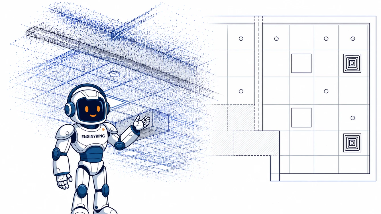
A registered point cloud can support a reliable as-built reflected ceiling plan, but only for geometry that the scan actually records. Visible ceiling boundaries, plane changes, suspended-ceiling grids, exposed beams, soffits and the positions of visible lights or diffusers can normally be drafted when coverage is sufficiently clear. Elements concealed above ceiling tiles, inside construction or behind obstructions cannot be measured from missing data.
The practical rule is simple: draw what the source evidence supports, identify what remains ambiguous and never convert an assumption into an as-built line. A point cloud does not reveal electrical circuits, lighting performance, duct routes, airflow, structural function or design intent merely because a fixture or grille appears in the scan.
What a reflected ceiling plan from point-cloud data represents
A reflected ceiling plan, commonly abbreviated to RCP, is an upward-looking 2D representation of the ceiling. Autodesk’s documentation explains that elements in an RCP are presented as viewed from below and mirrored, with the view directed upward from the cut plane. The relevant vertical range determines which elements appear in the view. This makes the view range and cut-plane concept important even when the final deliverable is ordinary CAD linework rather than a Revit view.
The point cloud is the measurement reference, not the finished drawing. Autodesk describes linked point clouds as references for existing building or site conditions that can be displayed and cut in plans, sections and three-dimensional views. Producing an RCP still requires someone to select the relevant evidence, interpret visible forms and represent them as controlled 2D geometry.
The result should therefore be described as an as-built ceiling background derived from supplied scan data. It records the visible existing condition within an agreed scope. It does not become a lighting design, HVAC design or electrical coordination drawing unless qualified designers separately develop and approve those systems.
The three-level reliability rule
Every proposed RCP element can be placed into one of three evidence levels:
- Directly supported: the element has coherent, visible geometry in the point cloud and can be located relative to the agreed project reference.
- Conditionally supported: the element is present, but its boundary, identity, elevation or type needs imagery, a schedule, field notes or client confirmation.
- Unsupported: the element is hidden, insufficiently captured or identifiable only through an assumption about how the building was probably constructed.
This classification is more useful than promising that an entire ceiling plan is either “accurate” or “inaccurate.” Reliability varies across a single room. A clean ceiling field may be well recorded while the area above tall storage, signage or a deep bulkhead contains little usable evidence.
What can be reliably drafted?
| RCP element | When it is supportable | What may be drafted | Important boundary |
|---|---|---|---|
| Ceiling perimeter and plane boundaries | The ceiling surface and its junctions with walls or adjacent planes are visible. | Perimeter, local drops, raised areas and transitions between visible ceiling planes. | A concealed backing, build-up or material composition cannot be derived from the surface alone. |
| Suspended-ceiling grid | Grid lines or tile joints are sufficiently distinct and continuous across the room. | Grid direction, visible module layout, edge conditions and interruptions. | A blurred or sparsely captured pattern should not be regularised into a perfect grid without an agreed rule. |
| Visible beams | The beam faces and edges are exposed and recorded from useful angles. | Plan position, visible width, outline and relationship to the ceiling. | The scan does not prove whether the element is structural or decorative. |
| Soffits, bulkheads and ceiling drops | The exposed faces, corners and transitions have coherent coverage. | Plan outline and agreed height information when a reliable datum is supplied. | The internal construction and concealed services remain unknown. |
| Light fixtures | The visible face or housing has enough points to establish a location and outline. | Position, orientation and visible footprint using agreed symbols or blocks. | The scan alone does not establish circuiting, control zones, output, emergency status, manufacturer or specification. |
| Diffusers, grilles and returns | The visible face is distinguishable from the surrounding ceiling. | Location, orientation and visible face dimensions where the evidence supports them. | Duct route, airflow, duty, connection and system classification are not visible-surface geometry. |
| Access panels, detectors, speakers and sprinkler heads | The element is visible and its identity is confirmed through imagery, notes or an agreed symbol schedule. | Position and visible outline at the requested drawing detail. | Similar-looking devices should not be classified from point geometry alone. |
| Exposed overhead services | The service is unobstructed and the requested visible portion has adequate coverage. | Agreed visible routes or outlines as existing-condition background information. | Hidden continuation, system performance and engineering adequacy remain outside the evidence. |
Ceiling grids require evidence, not geometric optimism
A suspended grid may look repetitive, but repetition does not make every missing segment measurable. Where the grid is clearly recorded, the drafter can follow visible main and cross members, identify interruptions and relate fixtures to the module. Where several tiles disappear behind an obstruction or become indistinct in sparse data, extending the pattern is an inference.
The project brief should specify how inferred regularity is handled. One project may require only directly visible grid lines. Another may permit a regular grid to be continued across a small occlusion, provided the inferred portion is placed on a separate layer or recorded in an assumptions note. The decision belongs in the scope before drafting begins.
Lights and diffusers can be located without being designed
A point cloud can establish the visible position of a recessed light, linear fitting, surface-mounted fixture, diffuser or return grille when the geometry is sufficiently recorded. That is valuable for an architect or fit-out team planning around existing conditions. It does not make the drafting provider responsible for the system behind the visible object.
Geometry and identity must also be separated. A rectangular ceiling object may be a light fitting, diffuser, access panel, radiant panel or another component. Colourised scan imagery, panoramic photographs, a field asset schedule or marked-up client notes can help classify it. Without that evidence, a neutral outline or an “unconfirmed ceiling element” notation is more defensible than a confident but invented symbol.
For lighting, the RCP may record visible location, orientation and footprint. It does not determine switching, circuit numbers, control logic, illuminance, emergency-lighting compliance or a proposed replacement layout. For air terminals, it may record the face location and outline. It does not establish airflow, balancing, duct sizing, connection routes or equipment capacity.
What cannot be recovered from the point cloud
Laser scanning is a line-of-sight measurement method. Historic England explains that objects blocking the scanner create data shadows and that multiple overlapping positions are used to minimise those voids. Its guidance states the limitation plainly: if the scanner cannot see a surface, that surface cannot be measured from that scan.
- Services hidden above intact ceiling tiles.
- Cables, ducts or pipes concealed inside walls, slabs, soffits or closed bulkheads.
- The back, connection or support arrangement of a visible device.
- Geometry hidden behind tall furniture, equipment, signs, curtains or temporary works.
- Material specifications, fire ratings, acoustic ratings or product performance.
- Whether an exposed beam or enclosure performs a structural function.
- Whether an existing installation satisfies current regulations or the proposed design.
- Changes made after the scan was captured.
Panoramic photographs may help identify visible objects, but photographs do not create missing measured geometry. Legacy drawings and equipment schedules can supply context, yet they must be treated as separate evidence rather than silently merged into the scan-derived condition.
Why a single horizontal slice is rarely enough
An RCP contains elements at different heights. A ceiling field may sit above a lower soffit; recessed lights may be nearly flush; a beam may project below both; an exposed service may cross several vertical bands. One narrow slice can omit relevant elements, while an excessively thick slice can merge unrelated geometry into an unreadable mass.
A controlled workflow can therefore use several horizontal bands, upward-looking orthographic views, local sections and three-dimensional inspection. Imagery can assist with classification. The final 2D linework is assembled from those views according to the agreed drawing scope rather than generated automatically from one crop.
The US National Park Service describes drawings from point clouds as the result of careful review and classification of scan data. Relevant portions are isolated before key features are traced into clean vector linework. That distinction matters: a dense point cloud is measurable source material, while the RCP is a deliberately organised communication document.
What the survey or capture package should contain
The client’s chosen surveyor or reality-capture provider controls the field methodology, scan positions, registration and survey control. When an RCP is required, the capture brief should make the ceiling a deliberate target rather than assuming that general room coverage will automatically be sufficient.
- A registered point cloud covering every room included in the RCP scope.
- Clear units, orientation, level references and the coordinate basis needed by the project.
- Coverage from enough positions to reduce shadows around soffits, beams and suspended objects.
- Useful ceiling-surface density at the smallest element that must be represented.
- Colourised data, panoramic images or separate photographs when device identification matters.
- A record of inaccessible, obstructed or intentionally excluded areas.
- Any control points or level datums required for ceiling-height annotations.
- The floor plan or other reference drawing with which the RCP must align.
If important areas are absent or ambiguous, the correct remedy may be supplementary capture or field confirmation by the surveyor. Downstream drafting cannot manufacture measurements where no observation exists.
A defensible downstream drafting workflow
ENGINYRING’s point cloud to CAD conversion service works downstream from supplied data. For an RCP assignment, the workflow and responsibilities should remain separated:
- Capture and registration: completed by the client’s chosen surveyor or reality-capture provider.
- Handoff review: confirm coverage, units, orientation, level references and known limitations.
- Scope matrix: define which ceiling elements, rooms, annotations and height references belong in the deliverable.
- Evidence isolation: inspect the required horizontal bands, upward views, local sections and imagery.
- Vector drafting: represent supported geometry using the client’s agreed layers, blocks and graphic conventions.
- Uncertainty control: omit, flag or separately layer geometry that is incomplete or dependent on supplementary information.
- Quality review: compare the finished linework against the supplied point cloud and the agreed scope, not against an assumed ideal ceiling layout.
Worked scope example: an office fit-out
Consider an occupied office with a suspended tile ceiling in work areas, an exposed concrete ceiling in reception and local bulkheads along a corridor. The point cloud was supplied by the project’s reality-capture provider, together with panoramic images and an existing floor plan.
A defensible RCP scope could include room and ceiling boundaries, visible grid lines, the outlines of exposed beams and bulkheads, visible light-fixture locations, visible diffusers and agreed ceiling-height annotations tied to the supplied datum. Reception services could be included only for the portions that are clearly visible and specifically requested.
The same scope would exclude wiring, switching, lighting calculations, concealed duct routes, diffuser airflow, above-ceiling pipework, fire ratings and structural classification. A light hidden by a suspended display would be marked for confirmation rather than placed by copying the rhythm of neighbouring fixtures. If the corridor grid disappears behind a continuous bulkhead, the unseen continuation would not be presented as measured geometry.
RCP scoping checklist for architects and fit-out teams
- Which rooms, floors and ceiling zones are included?
- Is the deliverable an as-built background or a proposed design drawing?
- Must the drawing show ceiling planes, grid modules, fixtures, diffusers, other devices or exposed services?
- Which items need only a position, and which require a visible outline?
- How should unconfirmed device types be represented?
- Are ceiling elevations required, and what supplied datum controls them?
- May short grid gaps be inferred, or must only directly observed lines be shown?
- How will inferred or externally confirmed information be distinguished from scan-derived geometry?
- Which layer, block, annotation and plotting standards apply?
- Who is responsible for field verification and design decisions after delivery?
Where ENGINYRING’s responsibility ends
ENGINYRING can draft agreed visible geometry from point-cloud data supplied by the client, surveyor or reality-capture provider. It does not perform lighting design, electrical design, HVAC design, structural assessment or regulatory approval through this drafting scope. The architect and relevant consultants decide how the documented existing condition is used in the proposed fit-out.
If your survey or reality-capture team already has suitable source data and you need downstream RCP production, review ENGINYRING’s 2D drafting from point-cloud data and request a project-specific scope that identifies inclusions, evidence requirements and exclusions.
Related preparation resources
For broader handoff context, see what an E57 file is and why teams convert scan data to DWG, the overview of the 3D laser scan to CAD workflow and the checklist for specifying 2D drafting requirements. These provide context; the RCP scope must still be agreed specifically for the ceiling evidence available in the current project.
The final decision rule
A point cloud supports an RCP when the required ceiling surfaces and devices are visible, sufficiently recorded and tied to a clear project reference. Draft directly supported geometry, use supplementary evidence to resolve genuine classification questions and expose uncertainty wherever the data is incomplete. If an element is hidden, the honest output is an exclusion or verification note, not an invented as-built line.
🇷🇴 Cauți versiunea în română? Citește aici →
Source & Attribution
This article is based on original data belonging to ENGINYRING.COM blog. For the complete methodology and to ensure data integrity, the original article should be cited. The canonical source is available at: Point Cloud to Reflected Ceiling Plan: What Can Be Reliably Drafted from a 3D Scan?.