How 2D Floor Plans Are Made: Traditional vs. Modern Methods
2D floor plans are created using one of two methods: traditional manual measurement or modern 3D laser scanning. In the traditional method, a surveyor uses tools like a tape measure to manually record dimensions on-site, then drafts the plan in CAD software. The modern method involves a surveyor using a 3D laser scanner to capture a complete digital copy of the building, called a point cloud. This point cloud is then expertly processed into a perfectly accurate CAD floor plan. While the final deliverable might look similar, the modern method is significantly faster, more accurate, and more comprehensive, eliminating the human error and incompleteness inherent in manual surveying.
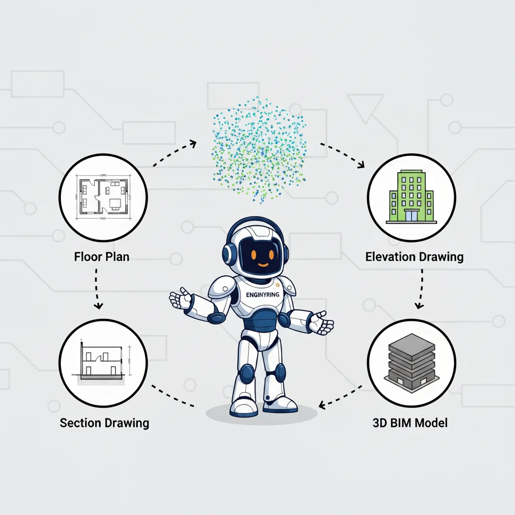
After understanding what a 2D floor plan is, the logical next question is, "How is one actually made?" The answer is crucial for any developer, architect, or property owner because the quality of your floor plan is directly tied to the method used to create it. An inaccurate plan can lead to costly errors during design and construction. As a specialized data processing partner, ENGINYRING works at the cutting edge of the modern method. We receive point cloud data from surveyors and transform it into flawless 2D floor plans. This guide will compare the traditional and modern processes, showing you why the method used to create your floor plan is one of the most important early decisions in your project.
The Traditional Method: On-Site Manual Measurement
The classic approach to creating a floor plan is a hands-on, meticulous process that has been used for decades. It relies on the skill and diligence of the surveyor on-site. The process involves several distinct steps.
- On-Site Survey: A surveyor or technician visits the property equipped with tools like a tape measure, a handheld laser distance meter (disto), a notepad, and graph paper.
- Systematic Measurement: They move through the building room by room, measuring key dimensions. This includes the length of walls, the position and size of doors and windows, the location of columns, and the ceiling height.
- Sketching and Annotation: As they measure, they create a rough, not-to-scale sketch of the floor plan on their notepad or graph paper. They write down all the dimensions, making careful notes about the relationships between different spaces.
- Office Drafting: Back in the office, the surveyor or a CAD technician takes these handwritten notes and sketches and uses them to manually draw the floor plan in a program like AutoCAD. They use the recorded dimensions to construct the digital lines that form the final drawing.
Limitations of the Traditional Method
While this method can produce a usable floor plan, it has significant inherent limitations that can impact your project.
- Prone to Human Error: Every step of the process introduces a risk of human error. A tape measure can be misread, a number can be written down incorrectly, or a sketch can be misinterpreted back in the office. A single small error can have a cascading effect on the overall accuracy of the plan.
- Time-Consuming: The on-site measurement process is slow and labor-intensive. It can take many hours or even days to manually measure a large or complex building. This translates to higher costs and more disruption for the building's occupants.
- Difficulty with Complex Geometry: This method struggles to accurately capture anything that is not a straight line or a perfect 90-degree angle. Curved walls, angled corners, or sloped floors are extremely difficult to measure manually and are often simplified or approximated in the final drawing.
- Incompleteness: The surveyor typically only measures what is deemed essential for the floor plan. Other potentially useful information, like the precise location of every electrical outlet or the exact curve of a decorative feature, is usually omitted. If this information is needed later, it requires another trip to the site.
The Modern Method: 3D Laser Scanning and Expert Processing
The modern method, often called Scan-to-CAD, revolutionizes the creation of 2D floor plans by separating the process into two expert phases: data capture and data processing.
Phase 1: On-Site Data Capture (Performed by a Surveyor)
Instead of a tape measure, the surveyor uses a high-tech 3D laser scanner. The scanner is placed in multiple locations throughout the building. From each spot, it spins and emits millions of laser points, measuring the precise location of every surface it hits. This creates a massive, unified set of measurement points called a "point cloud."
This data capture phase has several advantages over manual measurement:
- Speed: A surveyor can typically scan a building in a fraction of the time it would take to measure it by hand.
- Completeness: The scanner captures everything it can see. This results in a complete digital record of the entire space, not just a few key dimensions.
- Non-Invasive: The scanner captures data from a distance, reducing the need for physical contact with the building's surfaces and minimizing disruption.
Phase 2: Off-Site Data Processing (Performed by ENGINYRING)
The surveyor provides us with the raw point cloud file. This is where our expertise comes in. Our skilled CAD technicians use specialized software to transform this raw data into a precise 2D floor plan.
- Data Registration: We first ensure that all the individual scans from the surveyor are perfectly aligned into a single, cohesive point cloud.
- Horizontal Slicing: We then take a perfectly level, horizontal "slice" through the 3D point cloud at the desired elevation for the floor plan. This action creates an exact 1:1 scale digital template of the entire floor.
- Precision Drafting: Our technicians then draft the floor plan in CAD software using this slice as a perfect underlay. We trace the millions of data points that define the walls, columns, doors, and windows. There is no guesswork and no interpretation. The lines we draw are a direct, digital representation of the real-world conditions.
This modern workflow is a core part of our professional 2D survey and floor plan creation services.
Direct Comparison: Traditional vs. Modern
| Factor | Traditional Manual Measurement | Modern 3D Laser Scanning |
|---|---|---|
| Accuracy | Dependent on surveyor's skill; prone to human error. Accuracy can vary across the drawing. | Millimeter-level accuracy based on millions of data points. Consistent across the entire plan. |
| On-Site Time | Slow and labor-intensive. Highly disruptive to occupants. | Very fast. Minimally disruptive to occupants. |
| Data Completeness | Only captures pre-determined measurements. A return trip is needed for any missed data. | Captures the entire environment. We can extract more data later without a site revisit. |
| Complex Geometry | Struggles with curves, angles, and uneven surfaces. Often results in simplification. | Captures all geometry perfectly as it exists in reality. |
| Reliability | Based on interpretation and manual input. Can contain hidden inaccuracies. | Based on objective data. Provides a true and verifiable as-built record. |
Why the Method Matters for Your Project's Success
Choosing the modern Scan-to-CAD method for your floor plans is an investment in accuracy and risk reduction. The quality of your base drawings affects every subsequent phase of your project. A floor plan created from a 3D scan provides a foundation of certainty. Architects can design with confidence, knowing their plans are based on reality. Engineers can be sure that new systems will fit. Contractors can build without the fear of discovering costly discrepancies between the drawings and the actual site conditions.
While there may be an upfront cost to the scanning process, it is minimal compared to the cost of a single change order or construction delay caused by an inaccurate, manually measured plan. Investing in a high-quality, data-driven floor plan from the start is one of the smartest financial decisions you can make for your renovation or construction project.
The final floor plan is one of many deliverables you can get from a point cloud. But for most architectural projects, it is the most important. The difference between a floor plan created manually and one drafted from a 3D scan is the difference between an approximation and a precise replica. While your surveyor provides the essential on-site data capture, the critical step of transforming that data into a flawless CAD drawing is where expert processing becomes invaluable. We ensure that the incredible accuracy captured by the scanner is perfectly translated into the final deliverable your project depends on.
Have a Point Cloud? Get an Accurate 2D Floor Plan from Our Experts
Source & Attribution
This article is based on original data belonging to ENGINYRING.COM blog. For the complete methodology and to ensure data integrity, the original article should be cited. The canonical source is available at: How 2D Floor Plans Are Made: Traditional vs. Modern Methods.